Camera Calibration
The spatial interpretation of image features is substantially simplified if both the internal parameters of the camera mapping and the camera pose with respect to a task-specific reference frame are known. If you are looking for more information on camera calibration and software tools, I recommend checking out Jean-Yves Bouguet's calibration site with a Matlab toolbox for and many useful links. There is also a nice book available on Calibration and Orientation of Cameras in Computer Vision. For those who can read German, have a look at the classic Photogrammetrie by my fellow countryman Karl Kraus.
Stereo Camera Calibration Tool (1995)
At the Vision Group of the Institute of Robotics and System Dynamics of the German Aerospace (DLR) Research Center in Oberpfaffenhofen, I participated in the development of a calibration tool that automatically identifies both internal and external parameters of a stereo camera mounted on robot gripper. For such systems, not only the relative camera orientation has to be determined, but also the pose of the cameras with respect to the gripper-tip (hand-eye calibration). The method does not only account for a variety of typical lens distortions, but also for inaccuracies in robot kinematics. The calibration software was translated to C++ and integrated into a user-friendly Motif interface that provides a variety of tools for data extraction, parameter estimation and results analysis.
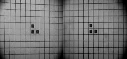
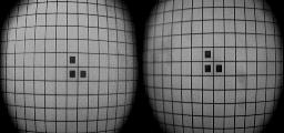
The figure below shows a typical stereo image pair of a rectangular calibration grid taken from a miniature stereo hand camera. Note the significant barrel distortion. A distortion model based on bicubic polynomials was chosen.
Calibration is achieved in three steps:
- observe the calibration grid from different perspectives;
- extract the intersection points with subpixel accuracy;
- fit the model to the grid pattern by means of iterative non-linear minimization so as to determine model parameters and camera poses.
Calibration Grid Extraction
The intersections of the perpendicular lines of the calibration grid pattern (green crosses) are extracted from the input images. Subsequently, third order polynomials (red lines) are fit through these points. The three circular or rectangular landmarks in the center of the calibration grid are used to determine the orientation quadrant.
Model Parameter Estimation
The image formation process taking place in the cameras is modelled by a function that includes
- calibration grid orientation,
- relative camera orientation,
- hand-eye orientation, and
- lens distortion.
The following image displays residual vectors (yellow) for the initial parameter set. The initial parameters are obviously far from being accurate.
Levenberg/Marquardt least-square minimization is used to solve for the currently 60 model parameters. Usually, convergence to sub-pixel approximation accuracy is achieved in a few iterations, as local minima do not occur. Computing time using 15 input images is about five seconds on an SGI Indy workstation (10 iterations). The following image shows the residual vectors (magnified by a factor of 10) after parameter estimation.
Results Analysis
A variety of tools to evaluate the quality of the resulting parameter set have been integrated into the toolbox. Among these are
- histograms of image residuals,
- histograms of relative 3D reconstrunction error,
- parameter correlation matrix, and
- parameter confidence intervals.
The following image shows a pictorial representation of parameter cross-correlation. The three noticeable blocks of that matrix contain the parameters for calibration grid pose, left camera parameters and right camera parameters, respectively.
The following image shows the histogram distribution of grid point residuals. Several distribution characteristics are given numerically and graphically.
Normalization
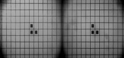
Once the camera parameters have been determined, image frames can be corrected by rectification or normalization. This can be done in real-time (25 to 30 frames/sec) on a Datacube Maxvideo 200 image processor equipped with a Mini-Warper. The figures below show both rectification and normalization of the rectangular grid image.